The smallest inter-frame gap in Fast Ethernet
Fast Ethernet in the form of 100BASE-TX is a very mature technology, although there were some hiccups in getting there. So it was surprising to me to find a way for the PCS receiver to accept an inter-frame gap shorter than the end-of-stream delimeter itself.
The 100BASE-TX Ethernet physical layer is broken up into several sub-layers:
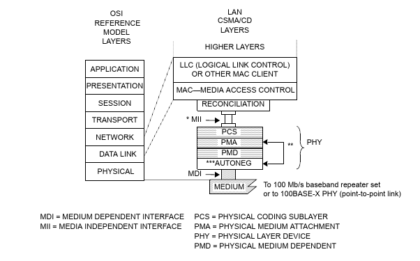
Working from the bottom up, the PMD converts analog signals from the medium to MLT-3 symbols (correcting for channel loss and baseline wander), decodes those symbols to bits, descrambles the bits, and then encodes the bits with NRZI. The PMA converts from NRZI back to bits[1] and performs some other optional tasks (such as far-end fault detection when using a medium without autonegotiation). The PCS performs 4B5B[2] alignment and decoding and generates data on the MII.
The PMA provides the PCS with a raw stream of bits. There is no indication of where one nibble begins and another ends. To recover this information, each nibble (4 bits) is encoded using 5 bits. Half of this encoding is used for data, but the other half is either invalid or used for control code groups. When no data is being transferred, the /I/ control code group (0b11111) is continuously transmitted. The control code groups /J/ and /K/ (0b11000 and 0b10001) form the Start-of-Stream Delimiter (SSD), indicating the start of a new frame:
To ensure that this sequence can always be recognized, all other code groups which (in combination with any other code group) could contain the sequence 0b1100010001 are invalid. The last control code groups to cover are /T/ and /R/ (0b01101 and 0b00111), which form the End-of-Stream Delimiter (ESD), indicating the end of a frame. By convention, /V/ is used for invalid code groups.
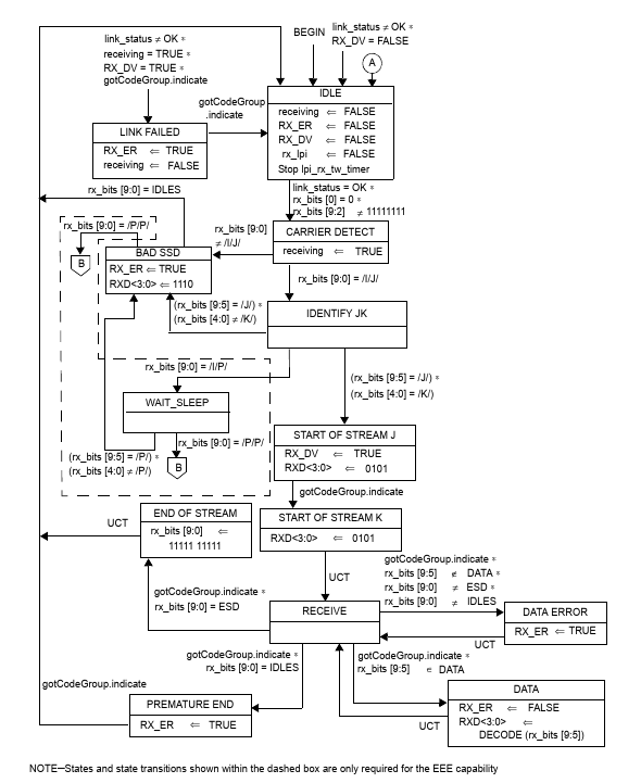
IEEE 802.3 specifies the PCS receiver through a state diagram. Each state
performs its actions continuously, and has several conditions leading to other
states. Conditions are formed of several comparisons or events, with *
expressing “and” (conjunction). All conditions are evaluated continuously
(more on this later), and sometimes there are uncontrolled transitions (UCTs),
immediately transitioning from one state to another.
The variables used in the above diagram are:
- link_status
-
Whether the link is up. For our purposes, we can assume that this is always true.
- rx_bits
-
The last 10 bits we have received. The least significant bit (0) is the most recent bit. These are not aligned, except when gotCodeGroup.indicate occurs. In that case, rx_bits[4:0] is the most recent code group, and rx_bits[9:5] is the next most recent.
- gotCodeGroup.indicate
-
This event occurs whenever there is a complete code group in rx_bits. It is automatically generated every five bits by the receive bits process (not shown). The initial alignment is determined by when RX_DV goes high.
- RX_DV
-
An MII signal indicating whether RXD is valid or not. This also determines the alignment of gotCodeGroup.indicate.
- RXD
-
An MII signal indicating the recieved data.
- RX_ER
-
An MII signal indicating there was an error.
- receiving
-
Whether we are currently receiving a packet.
- rx_lpi
-
This is only used for Energy-Efficient Ethernet (EEE).
Let’s add some of these signals to the SSD diagram from before:
There are a few important things to note here. First, note that there is an instant transition from CARRIER DETECT to IDENTIFY JK. This is because one of the conditions for exiting CARRIER DETECT will always be true, and both will be evaluated immediately. Second, although state and gotCodeGroup.indicate are shown as having transition times, they are really instant from the state machine’s point of view. In particular, gotCodeGroup.indicate is only true for one instant. If a state and its successor both depend on gotCodeGroup.indicate to transition, they can’t both transition off of the same gotCodeGroup.indicate event. If implemented in hardware, states like CARRIER DETECT should be viewed more as “superstates” (a la superclass) rather than states proper. The last thing to note is that there’s a delay of two code groups between when the first bit of a code enters the PCS and when the data gets signalled on the MII.
Now, lets’s look at the end of a packet:
Note that like CARRIER DETECT, END OF STREAM instantly transitions to IDLE, but not before setting rx_bits to all 1s. This is as if we had already been sending /I/I/ instead of /T/R/. We can abuse this to create (through non-standard coding) the shortest possible inter-packet gap. The following diagram shows the contents of rx_bits after END OF STREAM as “virtual” bits. It also shows the actual received bits as “real” bits:
A fully-compliant 100BASE-X PCS will exactly follow the state transitions in the diagram above, allowing an inter-frame gap of just 0.8 octets.
It appears that the designers of the PCS state machine wished to allow back-to-back frames (e.g. /T/R/J/K/)[3]. If this is indeed the case, we need to be careful when fixing the state machine. We could omit the clearing of rx_bits, but this would cause us to erroneously transition to BAD SSD (as we would transition to CARRIER DETECT when rx_bits[9:0] = /R/J/). Adding a condition on gotCodeGroup.indicate would not work for similar reasons. Instead, we should add an intermediate PRE IDLE state after END OF STREAM. This state would set receiving, RX_ER, and RX_DV to FALSE. It would transition to IDLE on gotCodeGroup.indicate.
In practice, this “bug” has no consequences. This is for three reasons. First, conforming PCSs can never generate this bit pattern. Second, conforming MACs use an inter-frame gap of at least 12 octets. And, third, most PCSs do not implement the specification exactly. This is because an exact implementation imposes difficult-to-meet timing requirements due to the tight coupling between the receive bits process and the recieve process. A typical implementation may register the outputs of the receive bits process, which does not allow for the instant feedback necessary to re-align the receive bits process and trigger the bug.